











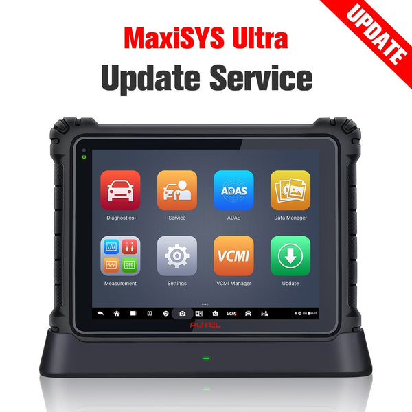



If your car exhibits symptoms such as the "Check Engine" light coming on or rough idling, use a automotive diagnostic tool to perform further diagnostics. By reading the trouble codes, you discover that P0021 appears in the list. The following message appears on the screen: "A Camshaft Position Timing Over-Advanced or System Performance Bank 2."
Simply put, the Engine Control Module (ECM) detects that the position of the vehicle’s second intake camshaft is earlier than the value set by the module. The intake camshaft is part of the variable valve timing system in modern engines; it improves engine performance and fuel efficiency by controlling the timing of the intake and exhaust valves. There are various reasons why its position may be abnormal.
This guide walks through a P0021 diagnostic procedure, from initial fault-code and freeze frame checks to electrical testing, oil system inspections, and mechanical checks. The Autel MK900BT is used for scan-tool operations, while additional tools and vehicle-specific service information are needed for further testing and repairs.

Quick Answer
The entire process can be summarized as follows: First, troubleshoot other malfunctions and basic electrical issues; then check the engine oil, solenoid valves, and diagnostic results. If the problem persists, conduct a thorough inspection of the wiring, oil pressure, oil passages, and mechanical components. Finally, verify the results of the repair.
For specific instructions on how to use the Autel scanner to perform diagnostics, see the detailed procedure below.
1. P0021 Detected: What to Check First
When you encounter code P0021, the first step is to check whether any other trouble codes are present. First, read all current trouble codes. If there are any trouble codes other than P000C and P0021, follow the corresponding procedures to address them first; if there are no other trouble codes, check the freeze frames.
Avoid assuming that P0021 points to a failed component. First, use a compatible diagnostic scanner, such as the Autel MK900BT, to review the freeze frame data. Available readings, including engine RPM, load, and coolant temperature, help establish the operating conditions when the code was set and guide further diagnosis.
2. Troubleshooting Electrical Issues in Cars
There are many causes of P0021, and among them, electrical issues are the easiest to diagnose and repair. The specific steps are as follows:
Step 1: Measure the ECM Output Voltage and Follow the Results
Turn the ignition switch on and measure the voltage between the ECM connector and the chassis ground.
- If the voltage is 10 V or higher, it indicates that the voltage at that location is normal. Next, check whether the issue is caused by a loose connection.
- If the voltage is less than 10 volts, check whether the solenoid valve is receiving power properly.
The inspection procedures for the two different scenarios mentioned here will be explained step by step in the following sections.
Step 2: Check for Loose Connections
The reason for this step is that, although the voltage readings are normal, there is a possibility that the connectors, wiring harness, or ground connection may be intermittently faulty. Further inspection of the ECM connectors and wiring harnesses is required to determine the specific issue.
Check the following items:
- Poor contact at the ECM connector
- Momentary open circuit or short circuit in the wiring harness
- Dirt, corrosion, or looseness at the engine ground terminal
If the inspection results indicate an abnormality, repair or replace the corresponding wiring harness or component. If no abnormalities are found, proceed to the next stage of troubleshooting.
Step 3: Check the Power Supply to the Solenoid Valve
If the voltage in Step 1 does not meet the specified requirements, check whether the power supply at the connector of the left intake oil control solenoid valve meets the requirements. This will help determine whether the issue involves the solenoid valve's power supply.
If the supply voltage is less than 10V, repair the power supply circuit. If the measured voltage is greater than or equal to 10V, this indicates that there is no abnormality here, and proceed to the next step in the inspection process.
2. Check Engine Oil, Solenoids, and VVT Performance
If no problems are found during the inspection of the above circuits, voltages, and other components, this indicates that the preliminary electrical inspection is normal.Aside from a potential electrical system fault, code P0021 may also be caused by low engine oil levels or a malfunction in the solenoid valve itself.
Step 1: Check the Engine Oil
Before conducting a thorough inspection of the components, address the issue with the engine oil itself first. Pay close attention to the following:
- Is the oil level within the specified range?
- Is the oil abnormally dirty?
- Has the oil solidified due to additives?
- Is oil of the specified viscosity being used?
If the engine oil condition does not meet requirements, adjust the oil level or replace the engine oil and filter, then continue with the diagnosis.
Step 2: Replace the Solenoid Valve and Read the Monitoring Values
If the voltage and engine oil condition are both normal but the trouble code persists, the solenoid valve must be replaced, and further diagnosis and inspection should be conducted based on the corresponding data.
1. Replace the left-side intake oil control solenoid valve. Use the Autel diagnostic tool to perform a [Clear Memory] procedure on the engine. Perform a driving cycle.
2. Use the Autel scanners to read the values for “VVT Monitor Bank 1” and “VVT Monitor Bank 2.”
Note: A diagnostic value of 0 indicates that the diagnosis is incomplete. Do not turn off the engine; repeat the driving cycle. The value updates continuously, so monitor the readings throughout the check.
3. Record the read values for “VVT Monitor Bank 1” and “VVT Monitor Bank 2.”
First, check the value for Bank 2. If the value is greater than or equal to 1,000, it indicates that the replaced solenoid valve is operating normally, but the trouble code still exists, so you need to continue troubleshooting other potential causes. If the value is less than 1,000, you need to continue comparing it with the value for Bank 1.
Step 3: Compare the Two Bank Values
Check whether the value for “VVT Monitor Bank 2” is less than or equal to 1000, and whether it is greater than (“VVT Monitor Bank 1” value × 1.5 + 100) when compared to the value for “VVT Monitor Bank 1.” If so, proceed to the next step in the in-depth troubleshooting.
If not, let the engine idle for 5 minutes, then replace (flush and replace) the oil filter and engine oil. Then proceed to the final verification.
3. Trace Wiring and Connector Faults
If the VVT monitoring results indicate that further diagnosis is needed, inspect the related wiring and connectors more closely. Start with physical damage and poor connections, then measure circuit resistance to check for open circuits or excessive resistance.
Step 1: Inspect Connections and Wiring Condition
Check the wiring and connectors at the ECM, oil control solenoid valve, camshaft position sensor, and crankshaft position sensor. Look for bent or damaged wiring and poor connections. Repair or replace any faulty components, then continue with the resistance checks below.
Step 2: Test Circuit Continuity
Turn the ignition switch OFF and disconnect the ECM connector. Disconnect the relevant component connector before measuring each circuit. Use the vehicle-specific wiring diagram to identify the correct terminals.
| Circuit | Measurement Points | Specified Resistance |
|---|---|---|
| Left-side intake oil control solenoid valve | Between the specified ECM and solenoid valve connector terminals | 1 Ω or less |
| Left-side intake camshaft position sensor | Between the specified sensor and ECM connector terminals | 1 Ω or less |
| Crankshaft position sensor | Between the specified sensor and ECM connector terminals | 1 Ω or less |
Test the circuits in the order listed. If a reading is 1 Ω or less, continue to the next circuit. If a reading exceeds 1 Ω, repair or replace the faulty wiring or connectors, then proceed to the final verification.
If all three circuits meet the resistance requirement, continue to the engine oil pressure inspection.
Note: The 1 Ω limit applies to this diagnostic procedure. These measurements check circuit continuity; they do not confirm sensor or solenoid operation or rule out intermittent faults and short circuits.
4. Investigate Oil Supply and Mechanical Faults
If no wiring faults are found, check the oil supply system and mechanical components for pressure problems, blocked passages, and camshaft binding.
Step 1: Check Oil Pressure and the Pickup Strainer
Check engine oil pressure against the vehicle specifications. If normal, inspect the timing chain cover oil passages. If abnormal, check the oil pickup strainer for foreign material. Clean it if contaminated; if no contamination is found, this procedure calls for replacing the timing chain cover before inspecting the camshafts.
Step 2: Inspect the Timing Chain Cover Oil Passages
Following the required engine removal procedure, inspect the oil pump inlet, outlet, and passages supplying both cylinder heads and the oil control solenoid valve. Check for missing O-rings and foreign material. Replace defective parts or the contaminated cover as specified, then continue.
Step 3: Check Camshaft Condition
Remove the timing chain as instructed and compare the turning resistance of all four camshafts. Check Bank 2 against Bank 1 for binding, contamination, scoring, and wear. Replace the affected camshaft and carrier if necessary, then inspect the remaining oil passages.
Step 4: Inspect Local Oil Passages and the Sprocket
Check the camshaft carrier, cylinder head, sprocket, and camshaft-end oil passages for blockages. If normal, replace the sprocket as directed by this procedure. If contaminated, remove the debris and replace the non-reusable camshaft carrier oil filter. After reassembly, idle the engine for 5 minutes, then replace the engine oil and oil filter. Proceed to the final verification.
Note: Follow the vehicle-specific service instructions for disassembly, pressure specifications, and sealant application.
5. Verify Repair Results
Use this final verification after the preceding diagnostic steps direct you here following repairs or an oil and filter change. It checks whether the VVT system now meets the monitoring criteria and determines whether the diagnosis can be completed or the procedure calls for ECM replacement.
Step 1: Re-check Bank 2 Values After Repair
Use the Autel scanner to perform a 【Clear Memory Mode】 on the engine again. Perform a driving cycle. Use the Autel diagnostic tool to read the values for “VVT Monitor Bank 1” and “VVT Monitor Bank 2.” Record and verify the readings for “VVT Monitor Bank 1” and “VVT Monitor Bank 2”:
- If the Bank 2 value is 1000 or higher, the ECM may need to be replaced.
- If the Bank 2 value is less than or equal to 1000, proceed to compare the Bank 1 value
Step 2: Compare the Final Readings for Both Banks
Compare the “VVT Monitor Bank 1” and “VVT Monitor Bank 2” values recorded in the previous step. If Bank 2 is below 1,000 but exceeds (Bank 1 × 1.5 + 100), this diagnostic procedure calls for ECM replacement. If this condition is not met and monitoring has completed, the results meet the procedure’s acceptance criteria, and the diagnosis is complete.
Final Thoughts
Using an Autel scanner, you can read and clear trouble codes, view freeze frame data, and access relevant information such as the VVT Monitor, helping you complete the entire diagnostic and repair process for code P0021. The use of automotive diagnostic tools improves the overall efficiency and accuracy of repairs. We hope this helps!


